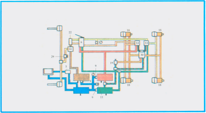
Air from the compressor is pumped into the supply tank (blue). Pressurized air moves from the supply tank to the primary tank (green), the secondary tank (red) and the front axle tank (brown) through one way check valves (9). When the air pressure reaches the governor cut-out setting (maximum 125 P.S.I.), the compressor cuts out and is in its cooling or ‘unloaded’ stage. When the air pressure drops approximately 20 P.S.I., the governor (5) returns the compressor to its pumping or ‘loading’ stage.
When a brake application is made by pushing down the dual foot valve treadle (6), air from the front axle circuit flows to the front axle relay valve and air from the primary and secondary circuits flows to the relay valves (14) at the rear axles. This control pressure on the relay valves causes the relay portion of the valves to open, relaying air pressure to the brake chambers. When the foot valve treadle is released, air pressure in the control lines between the foot valve and relay valves is released through the exhaust ports in the foot valve. Air pressure in the brake chambers is released through large exhaust ports in the relay valves.
Should either the primary or secondary SUPPLY circuit fail, the remaining circuit is isolated and continues to have braking ability.
When either of the primary or secondary SUPPLY circuit fails, braking on the front axle and one rear axle will not be affected due to the two way check valve (22) installed be tween the two service circuits.
Should a failure occur in the front axle circuit, the primary or secondary circuit will not be affected.
NOTE: A failure in any of the circuits will activate the low air warning system (11) and the driver MUST stop the vehicle to determine the cause. Should the air in the supply system drop to approximately 35 P.S.I., the spring brakes will apply
In this diagram the vehicle is equipped with a variable front wheel limiting valve (29). The application pressure delivered to the front axle is determined by the setting made by the driver.
To apply the spring parking brakes (18), the driver must move the control valve (19) to the ‘park’ position. This exhausts the control pressure from the spring brake relay valve (30), which then releases the air from the spring brakes, allowing them to apply.
To release the spring parking brakes, the driver must move the control valve to the ‘release’ position. This directs air to the spring brake relay valve, which supplies air pressure to the spring brakes, compressing or ‘caging’ the springs and releasing the brakes.