Compressed air is the means of transmitting force to an air brake system. The source of the compressed air is the compressor. A compressor is designed to pump air. Air pumped into a tank will result in pressurizing the air, as was explained previously in this manual.
A piston type compressor operates on a similar principle to that of the intake and compression strokes of an engine.
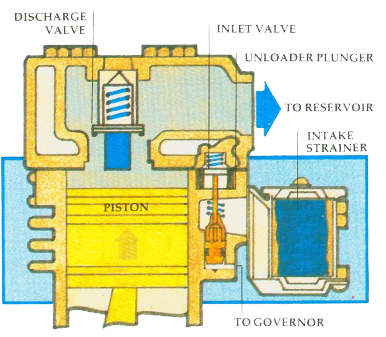
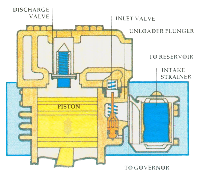
INTAKE STROKE: The downward stroke of the piston creates a lower pressure within the cylinder than the atmospheric pressure outside the compressor. This causes air to flow past the inlet valve (which the atmospheric pressure has opened) into the cylinder.

COMPRESSION STROKE: The upward travel of the piston compresses the air in the cylinder. The rising pressure cannot escape past the inlet valve (which the compressed air has closed) and as the piston nears the top of the stroke, the pressurized air is forced past the discharge valve and into the discharge line leading to the reservoir.

UNLOADING: When sufficient pressure has been built up, the compressor goes into an ‘unloading’ stage. The unloader plunger holds the inlet valves off their seats until pressure drops to the pre-set cut in pressure which is regulated by the governor.

The compressor is driven by the vehicle’s engine, by either belts and pulleys or shafts and gears. In vehicles which the compressor is driven by belts, the belts should be checked regularly for cracks and tension. Belt adjustment is usually checked by pressing with a finger midway between the pulleys. A greater distance between the pulleys will affect the amount of permissible slack. If the belts become too slack, they could slip, and the compressor will not achieve its maximum efficiency. While checking the drive belts also check the compressor for broken mounting brackets or loose mounting bolts.
The compressor is in constant drive with the engine. Whenever the engine is running, so is the compressor. It is usually lubricated from the engine lubrication system. Some compressors are self-lubricating and require regular checks of lubricant levels.
There are periods of time when it is not necessary for the compressor to pump air. A common pressure in an air brake system is from a low of 85 P.S.I. to a high of 105 P.S.I. Some systems operate between 105 P.S.I. and 125 P.S.I. Minimum pressure is approximately 20 P.S.I. below maximum pressure.
When the pressure has reached the system’s maximum, the compressor goes into an ‘unloading’ stage.
Most compressors have two cylinders. In the unloading stage, the inlet valves are held open, allowing the air to be pumped back and forth between the two cylinders, instead of compressing it. During the ‘unloaded’ stage, the compressor is able to cool.
It is most important that the air in the air brake system be kept as clean as possible. Dirt in the system can cause trouble.
The air from the atmosphere that enters the compressor must first pass through a filter to remove any dust particles from the air. The air filter must be cleaned regularly. A dirty filter will restrict the flow of air into the compressor, reducing its efficiency. Some vehicles have the inlet port of the compressor connected to the air cleaner of the vehicle’s engine.
A governor controls the minimum and maximum air pressure in the system. As the compressor is in constant drive with the engine, the governor’s job is to ‘unload’ the compressor when the desired pressure is reached. The governor does this by directing air pressure to the inlet valves of the compressor, holding them open when pressure in the system reaches its maximum. When the pressure in the system drops by approximately 20 P.S.I., the governor allows the inlet valves to close, returning the compressor to its pumping stage.
