This is an example of a tractor protection valve, which is usually mounted on the cab or chassis of the tractor.

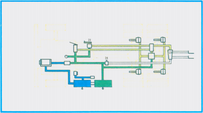
The diagram below illustrates a tractor unit equipped with a trailer supply valve (24) and a tractor protection valve (23). The trailer is not coupled and the tractor is being operated as a single unit. The driver has not opened the trailer supply valve (24) and the hand valve (21) is closed.


In the diagram above, the driver has made a brake application with the foot valve (6), and application air is being delivered to the tractor brake chambers. The two-way check valve (22) has shifted to the low pressure side, allowing application air in the control line to reach the tractor protection valve (23).
There is no air loss from the tractor through the disconnected glad hands (20).
If the driver, by mistake, applied the hand valve (21), with the trailer disconnected, the application air directed to the tractor protection valve would also be dead-ended. Again, no air loss would occur if the trailer supply valve (24) is in the closed position.