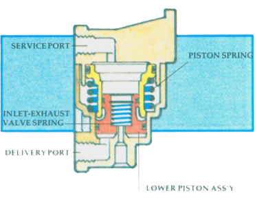
For better steering control on a slippery road surface, it can be an advantage to reduce the braking effect to the front wheels. This can be accomplished by installing a control valve (15) in the cab, and a FRONT WHEEL LIMITING VALVE (16) on the front axle.
The driver places the control valve in the ‘normal’ position for dry road surfaces and the front braking application pressure is normal. On a slippery road surface, the driver may flip the control valve to the ‘slippery road’ position. In this position, the control valve will cause the LIMITING VALVE to operate. Application air pressure to the front wheels is then reduced to 50 per cent of the application air pressure being delivered to the rear brake chambers.

Some systems are equipped with an AUTOMATIC LIMITING VALVE (17).

This valve will hold off brake application to the front wheels from zero to 10 P.S.I., depending on how it has been preset. Between the preset pressure and 40 P.S.I. of brake application, the reduction is approximately 50 per cent. Brake applications between 40 P.S.I. and 60 P.S.I. are reduced by less than 50 per cent. Brake applications over 60 P.S.I. are not reduced, full application is directed to the front wheels.

CHECK YOUR UNDERSTANDING
From the above diagram name each numbered component and briefly describe its function in the system. Write your answers on a separate sheet of paper.